
Push buttons are present in everyday life, from TV remotes to Elevators.
They allow the user to interface with a computing/electronic system by means of a button press.
The reason for using the push button in the system is of course dependent on the application it will be used for.
But, do push buttons need resistors? Push buttons do not require resistors all the time. There are certain instances when you will need resistors, and certain instances when resistors are not needed.
However, more often than not, a push button will require a resistor.
A push button will need a resistor when it is used in conjunction with a microprocessor or microcontroller as an input. The main reason for using it is to ensure a defined state (0 or 1) is present at the micrcontroller’s input, otherwise the input could be left floating (which is unwanted).
I will explain this in more detail below.
Applications where a push button will need resistors?
Let’s take a closer look at the different applications when a push button might require a resistor.
When using a push button with a microcontroller
Microcontrollers are essentially a small computer on a metal-oxide-semiconductor (MOS) integrated chip (IC).
They have many functionalities which include things like;
- Analog-Digital-Converter
- Timers
- Serial Communication
- Pulse Width Modulation
- General Purpose Input/Output Registers
The last one on the list is what we are concerned with when it comes to using push buttons.
General input/output registers are digital pins on a microcontroller that can either be used as an Input or an Output which can be controlled by the user via software.
This is how the microcontroller interfaces with the outside world.
Inputs include things like buttons, switches, and sensors.
Outputs are things like motors, displays, and Light Emitting Diodes.
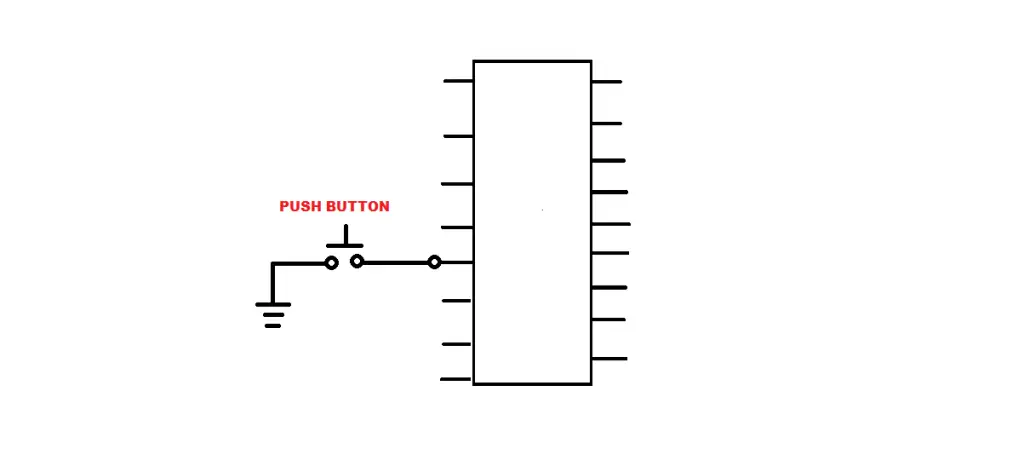
Below is a pic of a simple push button connected to a microcontroller as an input.
When it comes to microcontrollers, the digital pins deal with two defined logic states which can either be a Low (0), or a High (1).
These logic states represent the maximum and minimum voltage levels used by the microcontroller. If the microcontroller is powered by 5V, and ground is 0V, 5V will represent a logic 1, while the 0V represents a logic 0.
Here the push button is connected as an input without a resistor present which can cause some issues as it can leave the microcontroller pin Floating.
A floating input has no defined state as it is not within the voltage ranges that define a logic High or Low.
It could also appear to be that the push button has been pressed which can falsely trigger the circuit.
So how does a resistor solve this issue?
Resistors are used to hold the microcontroller’s digital pin in a defined state (0 or 1) depending on the configuration and prevent it from floating.
There are two typical configurations when using a resistor and push button; Pull-up and Pull-Down as seen in the diagram below.
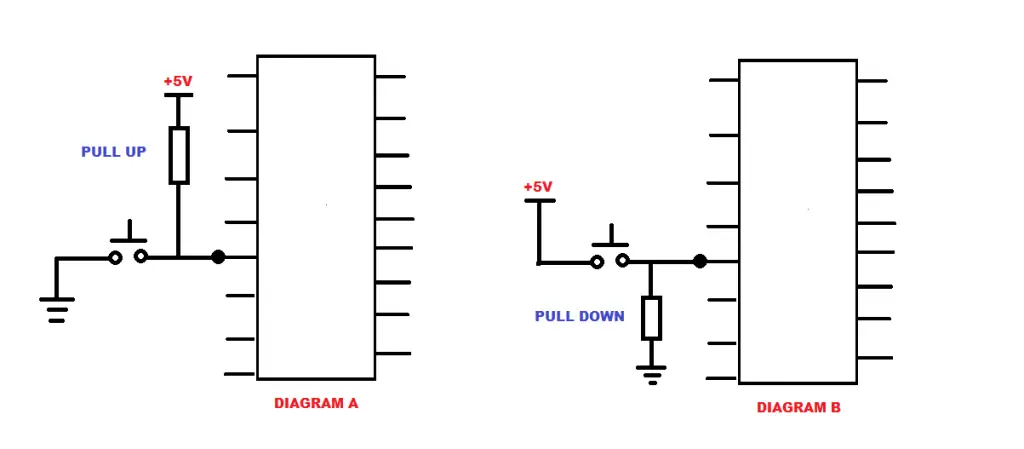
Push button and resistor in Pull-Up configuration
The first configuration is Pull-up as seen above in diagram A.
In this configuration the resistor is tied to the supply voltage (5V) and the push button.
What this means is that when the push button is idle (not being pressed) the input of the microcontroller is a Logic 1 due to the fact that it is tied to the supply voltage via the resistor.
When the button is pressed only then is Logic 0 presented at the input of the microcontroller.
Push button and resistor in Pull-Down configuration
The Pull-Down configuration can be seen in diagram B.
In this configuration, the push button is connected to the supply voltage, whereas the resistor is connected to ground between the push button and the microcontroller.
When the push button is idle, the input of the microcontroller is a Logic 0 as it is connected to ground via the pull down resistor.
Pushing the button will connect the input to the supply voltage thereby changing its logic state from 0 to 1.
The main purpose of both the configurations is to hold the input of the microcontroller in a defined state when the push button is not being pressed avoiding floating voltages.
Another instance when you might need resistors with a push button
Other than using a push button with a microcontroller, there is another instance when you might need a resistor in conjunction with a push button.
Say you are building a simple Light Emitting Diode (LED) flashlight.
All it requires is a push button and an LED. However, you might also require a resistor to limit the current to the LED.
But, saying this, the resistor is needed for the LED and not for the push button.
This could entail any simple circuit where a push button is used to provide momentary power to a device or component. The resistor is only needed as a means of limiting the current to the output device.
Do you need a resistor to limit current flow to a push button?
But does a push button require a resistor to limit the amount of current it can handle?
No, it does not require a current limiting resistor.
Like many other components, push buttons come with maximum voltage and current ratings.
These are the maximum values that they can operate within before they fail.
So, you will need to know the maximum voltage and current values your system will encounter so that you can choose a push button that can have ratings that match that or are higher.
What value resistor do you need for a push button?
Choosing the right value for a pull-up or pull-down resistor comes to a couple of considerations which include; power wasted and noise generated.
The size of the resistor should be so that it does not waste a great amount of power while not generating any noise.
Any resistor from 100 ohms to 10M will work adequately, but a 10K resistor is the go to when it comes to protecting against noise and also not wasting any power.


