

Whether you are building an electronic circuit, or are using an electronic device (like a mobile phone), a Capacitor is no doubt going to play a part in the working of that circuit.
A capacitor is an electrical component that generates an electric field between its plates when a voltage is applied to its terminals.
This electric field can then store electrical energy which can be used later.
How much electrical energy a capacitor can store is determined by its Capacitance.
The higher the capacitance, the more energy it can store and vice versa.
But, should capacitors have continuity? Capacitors should not have continuity. However, when testing the capacitor using the continuity function of a multimeter you might get intermittent ‘beeping’ due to the capacitor charging and discharging. Note, this does not indicate that the capacitor has continuity.
If there is a constant ‘beeping’ from the multimeter, this shows that there is continuity in the capacitor which means that it is faulty.
Read on for more information why a capacitor should not have continuity.
Brief look a the capacitor
Let’s take a brief look at the capacitor, which will give you a better understanding as to why it should not have continuity.
Capacitors are one of the three fundamental passive components used in electrical and electronic circuits (the other two being resistors and inductors).
As mentioned above, the capacitor has the ability to store energy in its electric field.
They have many applications in a circuit with the most common being energy storage, voltage spike suppression and signal filtering.
There are two types of capacitors; Polarised and Non-Polarised.
A non-polarised capacitor is like a resistor and the orientation of its terminals does not matter when placing it in a circuit.
Polarised capacitors however, have a positive and negative terminal, which means that they must be placed the right way round in a circuit.
The basic construction of a capacitor
A capacitor is constructed using two metal plates which are separated by an insulating material known as the dielectric as seen in the diagram below.
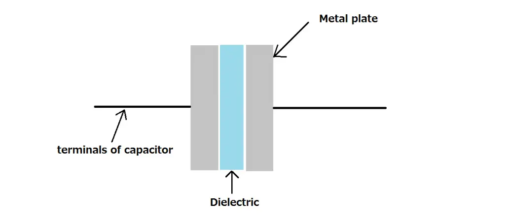
The dielectric can be a range of insulating materials (inhibits the flow of current) which can include;
- Air
- Paper
- Glass
- Rubber
- Plastic
- Ceramic
While the two metal plates are made from conductive materials (allows the flow of current) and can include metals such as;
- Aluminium
- Tantalum
- Silver
- Copper
What is electrical continuity
Say you are crossing a bridge over a river.
If you can get from one side of the bridge to the other without falling into the river, the bridge’s path is said to be Continuous.
Now, imagine there is an earthquake which splits the bridge in half.
You will not be able to cross the bridge safely as the path is no longer continuous
Electrical continuity pertains to the electrical and electronics world which states that for current to flow, it requires a complete path.
In the above analogy the bridge would represent an electrical wire, and you crossing the bridge would represent the electrons flowing through that wire.
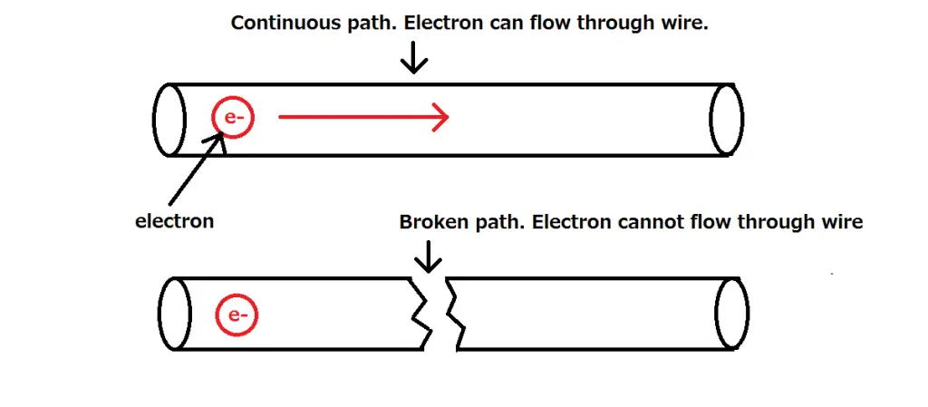
Just like our analogy, if there is a break in the path the electrons will not be able to flow from one end of the wire to the other.
What materials have electrical continuity
Electrical continuity exists in materials that are conductive.
A conductive material is something that is effective at transferring or ‘conducting’ heat and electricity.
This means electrons are loosely bound to their atoms within the material allowing them to move more freely.
Metals are very effective conductors and are the main reason they are used in electrical and electronic circuits.
Metals such as copper, silver, gold, tin, lead etc.
Insulators on the other hand are poor conductors.
The electrons of the atoms within the material are held more tightly making it harder to transfer electrons (electricity and heat).
Continuity of the Multimeter
The multimeter is an electronic measuring instrument that is used daily for troubleshooting and analysing electrical and electronic circuits.
Depending on the complexity of the multimeter, it can have the following functionalities;
- Read DC voltage
- Read AC voltage
- Test current
- Measure resistance
- Check diodes
- Transistor testing
- Continuity
The most basic of multimeters will have the ability to test continuity which is what we are concerned with.
The continuity symbol on a multimeter is shown using a sound wave (like that emitting out of a speaker symbol), as it uses a beeping sound to indicate continuity.
So how do you test continuity using a multimeter?
Say you have a piece of wire (like in the picture below), and you want to test whether that piece of wire is continuous from one end to the other.
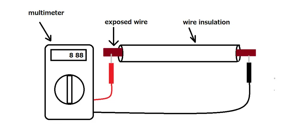
- First set the multimeter to the continuity setting
- Place one probe (negative or positive. The polarity does not matter), on one end of the wire (if the wire is insulated you will need to strip it first and place it on the conductive part of the wire).
- Place the second probe on the other side of the probe.
- If the wire has continuity the multimeter will produce a constant ‘beep’.
- If there is no continuity, there will be no beep
Note, if the material is somewhat conductive, there won’t be a beep but a resistance which will be displayed on the screen.
Why a capacitor should not have continuity
Now that we know the construction of a capacitor and how continuity works, we can take a look at why a capacitor should not have continuity.
The multimeter will only beep when a path is conductive and continuous.
We saw that a capacitor consists of two metal plates separated by an insulating material, therefore a continuous, conductive path does not exist within the capacitor therefore it will not have continuity.
However, you might get intermittent beeping when first testing a capacitor.
This happens because the multimeter uses a small current to test resistance (and continuity is pretty much a really low resistance reading).
So when the probes are placed on the capacitor, the capacitor will start charging (due to the current) causing the beeping sound due to a small resistance present.
But, this does not mean that the capacitor has continuity.
What happens if a capacitor does have continuity
If for some reason your multimeter has a constant beep when testing the continuity of a capacitor, this could indicate that the capacitor is faulty.
If the dielectric inside the capacitor has ruptured causing the metal plates to touch, this will create a continuous path.
But, you will not be able to use the capacitor anymore.
How to protect capacitors from getting continuity
A faulty capacitor might have continuity as the two metals inside might be touching.
But, this is not good as you will not be able to use the capacitor again.
There are couple reasons a capacitor might become faulty;
Static electricity
If you handle the capacitors without an Antistatic Wrist Strap you run the risk of damaging it through static electricity.
An Antistatic Wrist Strap reduces or removes electrostatic discharge which is the buildup of static electricity.
Static electricity can damage electronic equipment like computer hard-drives and even ignite flammable liquids.
Exceeding maximum voltage and current ratings
Every capacitor has a maximum voltage and current rating.
These ratings let you know what maximum values of voltage and current it can handle before failure.
So, be sure to check your capacitor ratings and stay below them.


