
A resistor has an important role to play in the electrical and electronic world and can be found in every circuit.
It is a passive component with the main job of providing ‘resistance’ in a circuit, hence the name resistor.
But, does a resistor reduce voltage or current? A resistor has the ability to reduce voltage and current when used in a circuit. The main function of a resistor is to limit current flow. Ohm’s law tells us that an increase in a resistors value will see a decrease in current.
To reduce voltage, resistors are set up in a configuration known as ‘voltage divider’. Also, with every component in a circuit, the resistor drops voltage across its terminals.
I will explain ohm’s law and how a resistor reduces current and voltage below.
How a resistor reduces current
The main function of a resistor is to limit or oppose the current flow in a circuit by providing ‘resistance’.
The best analogy for this is a garden hose that has water flowing through it. The water represents current.
If you happened to squeeze the garden hose you are going to provide a ‘resistance’ and limit the flow of water. The more you squeeze it, the less water can flow.
You squeezing the garden hose represents a resistor which does the same thing in a circuit.
How a resistor is constructed that makes it reduce current
The main way a resistor reduces current is through its physical construction and the materials used internally.
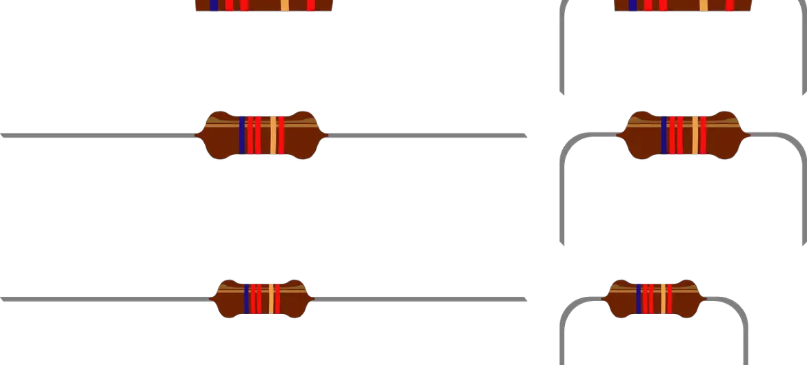
There are many different types of resistors available each being constructed a certain way. Below are some common resistor types:
Carbon – This type of resistor is known as a Carbon Composition Resistor (CCR). Inside this resistor is a solid cylindrical resistive element which is a mixture of finely powdered carbon and an insulating material. Increasing the mixture of carbon reduces the resistance, as carbon is a good conductor.
Carbon pile – This kind of resistor uses stacks of disks which are made of carbon to reduce/oppose current. These disks are compacted inside the body of the resistor between two metal plates.
Carbon film – A carbon film is placed on an insulating material with a helix cut into it to create a long, narrow path that will reduce current. Varying the shape and size will provide a range of resistance values.
Metal film – Many through hole resistors are made of a metal-film. They are coated with nickel chromium (NiCr).
Metal oxide – These types of resistors are made of metal oxides, which allows the resistor to withstand much higher temperatures.
Wire wound – This resistor reduces current by using a metal wire wound into a coil. The metal used is usually nichrome wound around a ceramic, plastic or fiberglass core.
Ohm’s law which determines how a resistor reduces current
To properly understand the relationship between current,resistance and voltage we need to learn about Ohm’s law.
This law was developed by Georg Simon Ohm in 1827.
Without getting into too much detail, he discovered that the amount of electrical charge through a metal conductor in a circuit was directly proportional to the voltage across it, which can be summarised by the equation seen below.
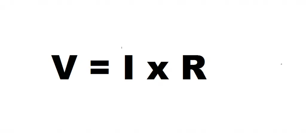
If we rearrange the formula we get resistance which is voltage divided by current.

You can see now the relationship between resistance and current is inversely proportional.
An increase in a resistors value will see a decrease in current thereby reducing it, while a decrease in resistance will cause an increase in current.
How a resistor can reduce voltage ?
Now that we know how a resistor reduces current, we can take a look at how it reduces voltage.
There are a couple common ways that a resistor can reduce voltage which include a voltage drop across its terminals, and a voltage divider.
First way a resistor reduces voltage : Voltage drop across its terminals
In the field of electronics, voltage drop occurs in every component that has a resistance. The voltage dropped across a component is governed by Ohm’s law.
For example, imagine we have a simple circuit consisting of the supply voltage and a lamp.
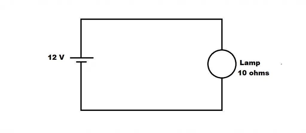
Here the Lamp has a resistance of 10 ohms (due to the fact that everything in a circuit has some form of resistance).
Since we know the voltage and resistance values, we can calculate the current using ohm’s law (I = V/R) which gives us a current of 1.2 amps.
So, this current of 1.2 A will be flowing through the lamp and powering it. If we take the current (1.2 A) and multiply it by the resistance of the lamp (10 ohms) using ohm’s law once again (V= IR), we get a voltage of 12 volts.
Therefore, there is a voltage drop of 12 volts across the lamp.
Now we know how to calculate voltage drop, we can take a look how this theory is applied to a resistor to reduce voltage.
If we replace the above lamp with a resistor of equivalent resistance (10 ohms) we are still going to get the same value of voltage dropped across it.
Now, we will add a second resistor ( R2 with a resistance of 5 ohms) in series with the 10 ohm resistor (R1).
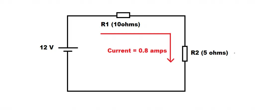
Just as with the lamp example, we need to find the value of the current flowing through the circuit.
This time the total resistance is the sum of the two resistors ; R1 (10ohms) + R2 (5ohms), which gives us a total resistance of RT = 15 ohms.
Now, using ohm’s law (I = V/RT) we get a current of 0.8 amps.
This current is the same current that passes through both resistors. With that we can calculate the voltage drop across each resistor giving us;
R1 Voltage drop = 0.8 x 10 = 8 volts
R2 Voltage drop = 0.8 X 5 = 4 volts.
Using ohm’s law we can find how much voltage a resistor reduces by dropping voltage across it as long as we know the supply voltage and total resistance.
The voltage drop across a particular resistance is governed by the current and the resistor’s resistance value.
Second way resistor reduces voltage : Voltage Divider
The second way a resistor can be used to reduce voltage is using a voltage divider. A voltage divider uses two resistors in the configuration seen below.

The output voltage at Vout is determined by the Vin, as well as the values of the two resistors (R1 and R2). The formula below is used to calculate the output voltage.
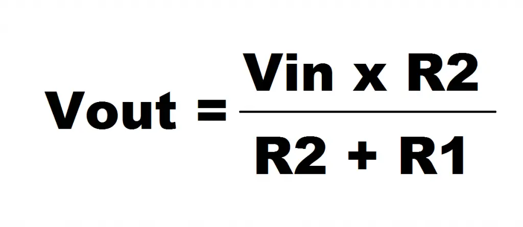
So for example, if the Vin is 5 volts, R1 is 10 ohms, and R2 is 10 ohms as well, if we use the equation we get an output voltage of 2.5 volts.
The great thing about this configuration is that we can select what voltage we want at Vout by rearranging the formula above to calculate the value of resistor R2 to give us our desired output voltage.

Say you need a voltage of 3 volts at Vout.
Using the rearranged formula we can calculate the value of resistor R2 to give us 3 volts. Using the same values for the Vin and R1, and the 3 volts for Vout, we get a value of 15 ohms for R2.
So you can see, this is a great way to use resistors to reduce voltage to your desired value.
Why do you need a resistor to reduce current?
The electrical and electronics world is filled with many different components and devices of varying shapes, sizes, functionalities etc.
Another thing that varies from one component to the next is its ratings. Every component has a maximum voltage and current rating.
These ratings should never be exceeded, as exceeding them could damage them.
So, a resistor is used in series with many components to reduce the current to avoid damaging them.
An example is a standard Light Emitting Diode (LED) which has a current limit of 20 mA. If a voltage supply is connected directly to the LED without the use of a current limiting resistor, you risk blowing the LED.
A current limiting resistor needs to be connected in series with the LED to reduce the current to below 20mA.
Why would you use a resistor to reduce voltage?
Having the ability to reduce voltage using a configuration like the voltage divider has many uses and applications.
Some common applications of reducing voltage include adjusting the level of bias of active devices in amplifiers and for measurement of voltages.
A multimeter also utilises voltage dividers.
Voltage dividers use resistors of fixed value to adjust the output voltage. However, if a variable resistor is used at R2, the output voltage can be varied by adjusting the variable resistor. A great application for this is volume control in a music system.
What are the different types of resistors used to reduce current and voltage?
As you saw earlier, there are many different ways a resistor is constructed.
Resistors come in a range of resistance values, sizes, shapes, and power ratings.
The two common types of resistor are Through Hole, and Surface Mount.
Deciding which of these to use depends on the type of circuit you will be using them in.
As there are low power and high power applications in electronics, there are resistors designed of different power ratings to be able to handle these powers.


