
A Zener diode is a variation of the diode.
It shares the same functionality as the original diode (which is to allow current to only flow in one direction), but with an added ability of allowing a large current to flow at a critical voltage.
Zener diodes are used in applications which include voltage regulation, being used as reference elements, surge suppressors, switching applications, to name a few.
But, do zener diodes have resistance and polarity? Yes the zener diode has resistance known as Rz, as well as having polarity (which means it can only be placed in a certain orientation in a circuit).
This article shall take a closer look at the resistance, and polarity of zener diodes.
What is a zener diode?
Zener diodes are designed to allow current to flow in the reverse direction when a certain voltage is reached.
It is a semiconducting device which consists of a heavily doped P-N Junction.
The advantage of the zener diode compared to the original diode is that it is able to provide a stable reference voltage. The voltage across the zener diode remains constant over a wide range of voltages.
This is the reason they are used regularly in voltage regulation applications.
What is resistance?
Let’s take a quick look at resistance which will help you understand how a zener diode has resistance.
However, if you are well versed with resistance, you can skip this section.
So what exactly is resistance?
Resistance can be seen as a force that opposes the flow of current. The more resistance the less current can flow, and decreasing the resistance allows more current to flow.
It is measured in Ohms with the symbol of Ω.
You might be familiar with the component known as a Resistor. This component has the sole function of limiting the flow of current.
Resistors have a known resistance.
However, every single material will have the ability to resist the flow of current. Some have higher resistance and they usually fall under the Insulator category. Materials like glass, paper, rubber, etc.
In the other category we have Conductors which are metals such as Gold, Silver, Copper, etc. These materials offer less opposition to the flow of current.
However, all metals do not have the same resistance, they vary from one to the next.
For example, copper has lower resistivity (offers less opposition to the flow of current) compared to aluminum and is why it is commonly used as a conductor in electrical and electronic circuits and components.
Resistance and resistivity of materials
As mentioned above, all materials have some sort of resistance.
The resistance of a material is given by its resistivity and is the physical property of the material. Resistivity and resistance are two separate entities and should not be confused as for one another.
Resistivity is defined as the amount of resistance a material has per unit length for a cross-section. The unit for resistivity is ohm-meter.
Whereas, resistance is the overall value of the material.
Do zener diodes have resistance?
So does a zener diode have resistance?
Yes, zener diodes have a resistance which is known as the zener diode’s internal resistance and can be viewed like a series resistor.
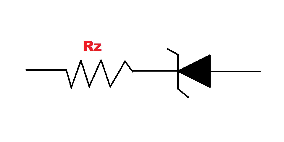
Where RZ is the zener diode’s resistance.
But how do they have resistance?
In a perfect world the zener would have no resistance, but, unfortunately, we do not live in a perfect world and it does have some internal resistance.
This comes down to what we have learnt about materials and how every single material has some sort of resistance (whether it be real small, or real high).
The construction of the zener diode will mostly be metal based, therefore it is going to have resistance, however, it will not be very high due to the zener diode’s physical size as well as which conductors are used to construct them (ones with lower resistivity).
What effects does this internal resistance have on the zener diode?
This resistance can be unwanted.
We stated earlier that the voltage across the zener diode is stable and does not vary. However, this is not entirely true.
The internal resistance of the zener diode is to blame here.
As current through the diode (Iz) rises, the voltage (Vz) rises as well because of the resistance and what we know of the Ohm’s Law.
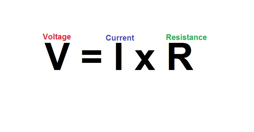
Current and resistance share a directly proportional relationship with voltage. As the current rises so too does the voltage due to the small resistance.
If the resistance was zero, a change in current would not affect the voltage as the total would be equal to zero.
Therefore the lower resistance of the zener diode the better.
What is the typical value of zener diode resistance?
There isn’t one specific company that manufactures all zener diodes. There are many companies who are involved in the process.
Therefore, zener diodes across companies will vary in many aspects such as what materials they use, as well as production methods.
Also, zener diodes come in a range of sizes.
So there isn’t one typical value of resistance across all zener diodes.
Zener diodes, like other components, come with a datasheet (that is provided by the manufacturer). Datasheets include important information about components.
The resistance Rz of the zener diode is one its important parameters and will be included in the datasheet. This value included is the maximum value of resistance.
What is polarity?
Next let’s take a look at whether a zener diode has Polarity.
So, what exactly is polarity?
Polarity is a term used across different disciplines such as chemistry, magnetism and electricity.
It is described as ; “a state or condition of an atom or molecule that exhibits opposite properties or powers in opposite parts or directions.”
For example, a magnet is known for having North and South poles. Here magnetic polarity refers to the orientation of these poles in space.
Electric polarity
But, when it comes to zener diodes, we are more concerned about electric polarity.
Voltage can be defined as an Electromotive Force (EMF) between two points. When we are talking about these two points, we are looking at which point has more electrons than the other.
The point that has more electrons is the Negative Pole, making the other point a Positive Pole.
Now when a conductor (such as wire) is used to close the path between the two poles, electrons flow from the negative pole to the positive pole (this flow of electrons is known as current).
An example of this is a battery which has negative and positive terminals (or poles).
Connecting a wire across the two terminals will cause electrons to flow from the negative terminal to the positive.
Components and polarity
So how does polarity pertain to electrical and electronic components?
They can be divided into two categories when it comes to polarity;
- Polarized or,
- Non-Polarized
Non-Polarised components do not have any polarity. These components can be placed in a circuit in any orientation without altering their functionality.
A resistor is an example of a non-polarized component.
Polarized components on the other hand have polarity. This means they have been constructed in a way where one of their terminals has more electrons than the other.
They will have one negative and positive terminal. Therefore they will have to be placed in a circuit in the right orientation (their terminals must match the terminals of the voltage source).
A common example of a polarized component is a battery.
Do zener diodes have polarity?
So, do zener diodes have polarity?
Yes, zener diodes have polarity and are classed as polarized components. One of its terminals will be negative, while the other will be positive.
The two terminals of the zener diode are known as the Anode and Cathode, where the anode is the positive terminal, and the cathode is negative.
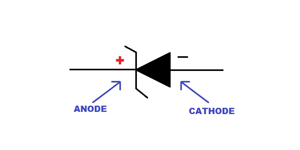
When biased in the forward direction, the cathode becomes negatively charged compared to the anode.
How do you identify the positive and negative terminal of a zener diode?
Since the zener diode has polarity, you will need to place it in the right orientation in order for it to function properly.
But how do you identify which is the positive and negative terminal?
Even if you picked up two diodes which were manufactured from separate companies, they would still use the same convention to identify the positive and negative terminal.
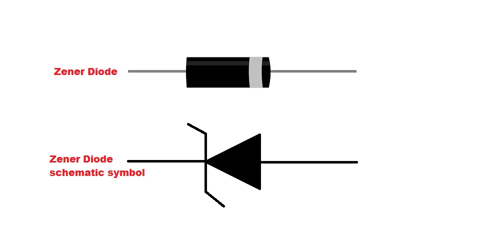
All diodes have a black band that is painted on the negative side of the diode (as seen in the image below). Or if the diode is black, it will have a silver or white band.
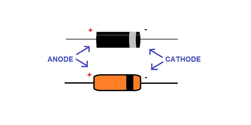
So, make sure that the side with the black band is connected to the negative rail of your circuit.


