

The electronic world is filled with a multitude of different components such as capacitors, inductors, transistors, integrated circuits, and much more.
Along with these components, are many different terminologies such as capacitance, inductance, current, voltage, power, etc.
You would be forgiven if you happened to confuse some of these components and terminologies.
One very common confusion is between a Resistor and Resistance.
Difference between a resistor and resistance
The difference between a resistor and resistance is that resistance is an electrical property that defines the ability of a component to ‘resist’ current. A Resistor is a component that is specifically designed to be able to limit current flow in electrical and electronic circuits. Resistors are created with a known resistance.
So, the main difference between a resistor and resistance;
- Resistance is an electrical property that all components/ materials have,
- Resistors are components designed with a known resistance having the sole purpose of limiting current flow in circuits.
A deeper look resistance
It will help to learn about resistance and a resistor separately before taking a look at the difference between them.
Let’s start with Resistance.
There are many instances of resistance outside the world of electronics.
Think about a river.
Imagine this river has no rocks so the water can flow at a steady pace with no interruptions. Now, let’s add some really big rocks. These rocks are going to provide a ‘resistance’ to the flow of water thereby slowing it down.
Electrical resistance in electronics is very similar. It is a property of material that opposes (or resists) the flow of electrons (or current).
The higher the resistance of the material, less current can flow, and the lower the resistance of the material, more current will be able to flow.
Materials can be classed into two categories; Conductors and Insulators.
Conductors are materials (such as gold, copper, aluminium, to name a few) that offer less resistance, therefore allow current to move more freely through them. This is why conductors are used to make wires and in the construction of electrical and electronic components.
Insulators on the other hand, are materials (such as glass, wood, plastic, etc) that have higher resistance and therefore inhibit the flow of current. In most cases no current can flow through them at all.
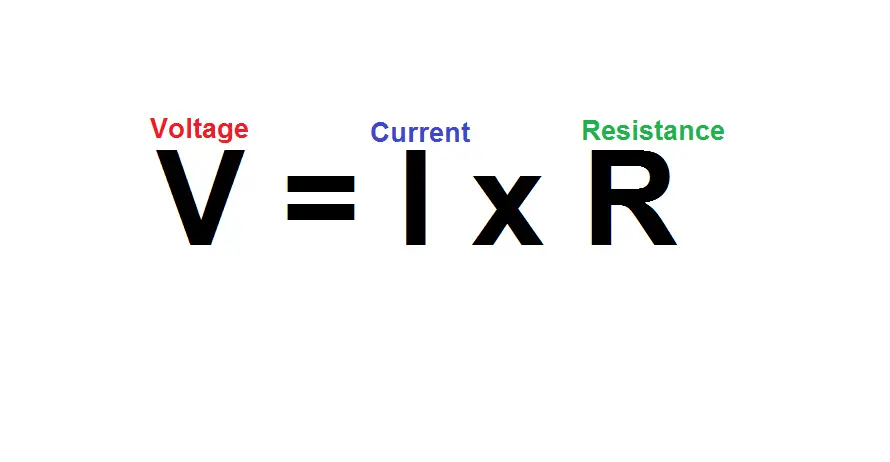
The discovery of resistance in electronics dates back to the early 1800s after a German physicist named George Simon Ohm learnt the relationship between Voltage, Current, and Resistance which he formulated into an equation known as Ohm’s Law.
These are three very important terminologies in the field of electronics (I would be surprised if you didn’t encounter any of them).
Resistance is measured in Ohms named appropriately after the man who discovered it.
Measuring the resistance of a given material
All materials are not made the same. As we saw above, some materials allow current to flow more freely (conductors), while others inhibit the flow of current (insulators).
But, all conductors do not have the same resistance. Resistance varies from one conductor to the next.
Lucky for us, there is an equation that enables us to calculate the resistance of conducting (and non-conducting) materials of given length and cross sectional area.
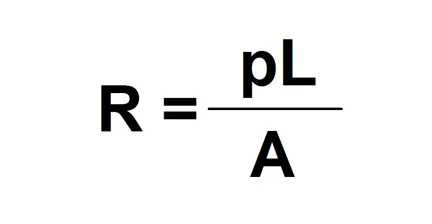
R = Resistance
p = Resistivity of material (temperature dependent) ( Ohm-meters)
L = Length of material (m)
A = cross sectional area of material (m2)
Let’s take a look at an example of three different materials and compare their resistance. Since length, and area of materials affect the total end resistance, we shall assume the length and area to be the same for all three materials.
The three materials shall be Gold, Copper, and Wood (two conductors and one insulator).
Finding the resistivity of materials is as easy as googling; “resistivity of gold” to find the resistivity of a given material, or you could just google “resistivity of materials” which should yield a table of the resistivities of many materials.
Resistivity of Gold = 2.44 x 10⁻⁸
Resistivity of copper = 1.68 x 10⁻⁸
Resistivity of wood = 1010
The Length for the three materials will be 20cm = 0.2m.
The Area for the three materials will be 15cm2 = 0.0015m2.
Note, when doing the calculations to find resistance, make sure your length and area values are in meters.
After using the equation, as well as the values for length, area, and resistivity, we get the following resistances for the different materials;
- Gold = 3.25 x 10⁻⁶ ohms
- Copper = 2.24 x 10⁻⁶ ohms
- Wood = 13.3 x 10¹¹ ohms
As you can see, the resistances of copper and gold are far lower than the resistance of wood.
This is the main reason you would use copper and gold circuits to allow current to flow, compared to wood (which wouldn’t let any current flow).
A deeper look at the resistor
Now that we know a bit more about resistance, let’s take a closer look at the Resistor.
There are many different types of components and devices in the electrical and electronic world, each with their own unique abilities which help perform a certain function within a circuit.
Components such as capacitors, transistors, inductors, integrated circuits, transformers, diodes, to name a few.
The Resistor is a fundamental electronic component that can be found in almost all circuits.
So what is the definition of a resistor?
A resistor is a passive electrical and electronic component, whose main purpose is to ‘resist’ the flow of current in a circuit. Also, rather than having an ambiguous resistance value, resistors are created with a set resistance value.
The bigger the resistance, the less current can flow, and the lower the resistance, the more current can flow.
It is known as a passive component due to the fact that it has no means of generating its own power, but rather dissipates power in the form of heat.
The ability to resist current comes down to what we just learnt in the previous section about the resistance of materials, and how the resistor is constructed.
Construction of a resistor and how it provides resistance
So, we know that conductors allow current to flow more freely compared to an insulator.
Under the umbrella of resistors, there are many different variations of how they are constructed and the materials used.
But, to save you time, I shall concentrate on the most common type which is the Wire-wound (other forms of the resistor shall be discussed later if you do want to learn a bit more).
Below is an image of what a wire-wound resistor looks like on the inside;
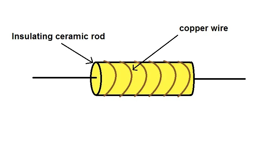
As you can see, there is a rod that is wrapped by a wire. The rod is typically an insulating ceramic, and the wire is copper (due to its great conductivity)
But, copper has low resistance! So, why use it in a component meant to resist the flow of current?
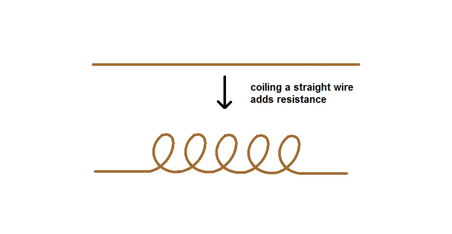
While resistors need to oppose the flow of current, they still need to let the current pass. But, just sticking a straight piece of copper wire inside a resistor is not going to add much resistance.
The key to increasing the resistance of a set length of copper wire comes down to coiling the wire. This is why the copper wire is wound (coiled) around the insulating material.
The resistance of a resistor can be accurately set by controlling the number of turns of the coil of copper wire (resistors come in a number of different resistance values, which I will talk about in more depth later).
Also, we saw the resistance of a material is controlled by a number of factors; length and cross-sectional area.
If the length of copper wire is set, we can further increase its resistance after coiling it by reducing its cross-sectional area (make it thinner). This is thanks to the inversely-proportional relationship between resistance and the cross-sectional area of a wire.
But, what if you want to reduce the resistance of a resistor?
Just do the opposite! Reduce the number of turns, and increase the cross-sectional area of the wire.
What is the difference between a resistor and resistance?
Alright, so we have had a quick look at both resistance and a resistor individually. You might have already got the jist of the differences between the two.
But, just in case you are still unsure, I will explain the main difference.
When we talk about electrical resistance, as we saw earlier, we are talking about a material’s ability to resist the flow of electrons (current).
All materials have electrical resistance,some have lower resistance (conductors) compared to others which have higher resistance (insulators).
Now, a resistor is an electrical component which is specifically designed to have a set value of resistance.
So, the main difference is that electrical resistance is a property that all materials have, and a resistor is a component that is designed with the specific purpose of implementing resistance in electrical and electronic circuits.
Sometimes these words can be used interchangeably and might be the reason you could be confused.
For example, you could say I require a resistor of 10 ohms, or a resistance of 10 ohms when designing a specific type of circuit.
Why are resistors important in electronics
But, why do we need resistors in the first place?
Every electrical and electronic component has something known as a Power Rating.
This is a value that indicates how much electrical power is needed by the component to work effectively.
Also, the power rating value indicates the maximum allowable electrical power the device or component can handle.
Exceeding this value will cause damage to the component.
The power rating can be broken further into; Voltage ratings, and Current ratings.
This is because power is a product of voltage and current ( P = V x I).
Components will have values for maximum voltage and maximum current ratings that should not be exceeded.
Resistors are important as they allow us to protect components in circuits by limiting the current so that the current ratings of that component are not exceeded (and therefore power rating as well).
Sometimes you might not be able to change the power supply (which means the voltage is fixed), so you will need a resistor to limit the other variable in the power equation (in this instance the current).
Different types of resistors and their resistances
There isn’t one specific type of resistor. Resistors primarily fall under two categories; Fixed value resistor and Variable resistors.
Each offers a range of resistance values. Let’s take a deeper look at both types.
Resistors with fixed value resistance
As the name might suggest, fixed value resistors have a resistance that is fixed regardless if there is a change in voltage.
It cannot physically change its resistance.
For example, if you bought a 10 ohm fixed value resistor, this is the only resistance that the resistor is going to be able to provide.
In an ideal world, the resistor would provide a fixed resistance at all times. However this is not the case, as their resistance varies slightly with temperature (which we shall look at later).
Fixed value resistors are the most commonly used in circuits. Their value is chosen during the circuit design phase using calculations such as ohm’s law.
Earlier we saw the construction of a wire-wound resistor. This is one of the most common fixed value resistors.
However, there are many other types of fixed value resistor available;
- Carbon composition
- Carbon film
- Metal Film
- Metal-oxide film
- Metal glaze
- Foil
Carbon composition fixed value resistors
Have a cylindrical form with metal caps at either end of the cylinder. Inside the cylinder is a substance that is a mixture of carbon power and ceramic.
While used primarily in the early 1960’s, this type of fixed value resistor isn’t used a lot anymore due to its high cost and low stability.
Carbon film fixed value resistors
Has a very similar construction to the carbon composition resistor. However, a carbon film is placed atop a ceramic substrate.
This type of fixed value resistor produces less noise when compared to carbon composition resistors.
Metal film fixed value resistors
The metal film resistor has the same construction as the carbon film. But, rather than using carbon as the material of the film, other metals are used.
Metals used in metal film resistors are usually Nickel Chromium, Tin or Antimony.
The resistance of metal film is less affected by temperature.
Metal oxide fixed value resistors
Has the same construction as carbon film, and metal film resistors.Again, what sets them apart is the material used.
The film in this resistor is a metal oxide such as Tin Oxide.
They cost less compared to carbon composition resistors, and can be used at higher temperatures.
Metal glaze fixed value resistors
Use a composition of glass powder and metal particles to restrict the flow of current.
Its resistance is also less affected by temperature.
Foil fixed value resistors
Last but not least are foil resistors.
They are made using an alloy (a material composed of two or more metallic elements). The foil is created from an alloy of nickel and chromium.
Of all the different types of construction for fixed value resistors, these are the most accurate and stable. They also produce far less noise.
Resistors that can vary their resistance
The next major type of resistor is the Variable Resistor.
This type of resistor has the ability to vary its resistance between two set values (with the lower usually being 0 ohms).
Note, this does not mean it’s restricted to those values, it can have a range of values which sit within the range of its lower and upper resistance limits. Its incremental value depends on the resolution of the variable resistor.
For example if you have a 10k variable resistor, you would be able to set its resistance at any value between 0 and 10k ohm. So, you could set it at 10, 100, 1k, 2.5k, 5.7k, 8k etc.
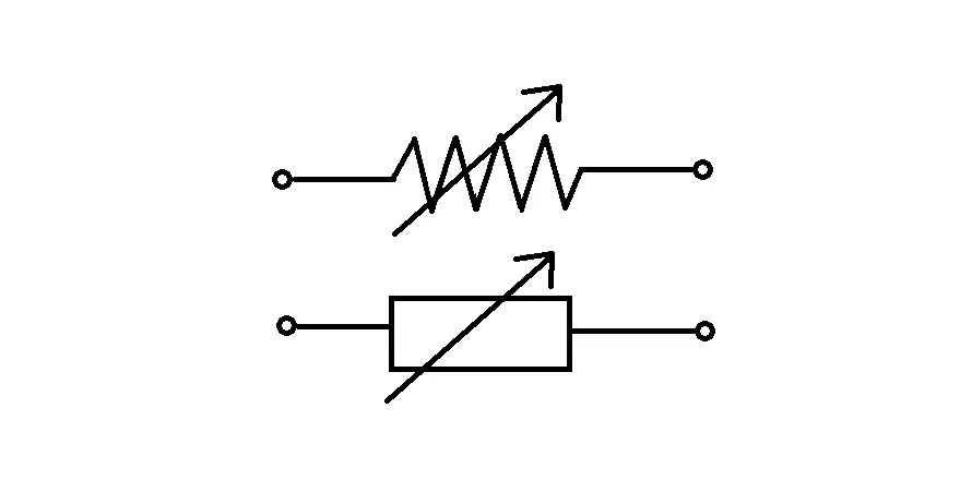
Below are the most commonly used circuit symbols for variable resistors;
The construction of a variable resistor is basically a fixed resistive element along with a wiper that sits on the resistive element.
The slider can be adjusted (by means of a slider or knob which you control) to sit anywhere along the resistive element thereby adjusting the overall output resistance.
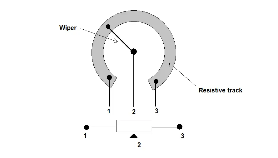
As you can see there are three terminals and the resistive element is connected to terminals 1 and 3. To use it as a variable resistor, you have to make connections to terminal 1 and 3.
The great thing about the variable resistor is that it has an added ability, which is to vary voltage. When used to vary voltage, it is known as a Potentiometer.
To use it as a potentiometer, you would connect terminals 1 and 3 to GND and VCC (it doesn’t matter which terminal gets connected to what). The varied voltage is then presented at terminal 2.
Other forms of the variable resistor
The variable resistor we just looked at is just one of the most common types which varies its resistance mechanically (twisting a knob, or moving a slider).
However, there are other forms of variable resistors each having its own unique way of varying resistance.
Let’s take a quick look at each of them.
Light dependent resistors
The first on the list are Light Dependent Resistors (LDRs).
However, they have many other aliases that you might know it by, which include, Photoresistor, Photocell, or Photoconductor.
The resistance of light dependent resistors changes depending on varying light levels. The amount of resistance that changes depends on the intensity of light, as well as the sensitivity of the LDR.
The less light that the LDR is subject to, the higher its resistance (in the order of megaohms) and the more light that shines upon the LDR, the lower its resistance (few hundred ohms).
They are created using a semiconducting material that gives them their light sensing abilities.
Common applications of the light dependent resistors;
- Smoke alarms
- Photographic light meters
- Streetlights
- Burglar alarms
Force sensitive resistor
Next up we have the Force Sensitive Resistor (FSR).
The resistance of the force sensitive resistor changes when it is subject to force, pressure or weight.
How much the resistance changes is proportional to the amount of force being applied.
When there is no force applied to them, it has an almost infinite resistance (which can be viewed as an open circuit).
When a light force is applied, the resistance ranges around 100kohm.
At maximum force, the resistance can be as low as 200 ohm.
Note, these values will vary from one FSR to the next.
FSRs can withstand forces up to 20lb (roughly 100 Newtons).
Common applications of force sensitive resistors;
- Midi controllers (for music producing)
- Electronic drum kits
- Electronic throttle and brake (automotive)
- Gaming joysticks
- Sports (target force and accuracy detection)
Thermistor
The Thermistor is a portmanteau of the words ‘thermal and ‘resistor’.
These words are chosen because of the fact that the thermistor is a device whose resistance varies depending on ambient temperature.
There are two types of thermistor; Negative temperature coefficient (NTC) and Positive temperature coefficient (PTC).
The relationship between resistance and temperature in NTC thermistors is inversely proportional. This means as temperature rises, resistance decreases, and vice versa.
In PTC thermistors, the relationship between resistance and temperature is proportional. So, when temperature rises, so does the resistance, and vice versa.
Common applications of thermistors;
- Fire alarms
- Refrigerators
- Ovens
- Digital thermometer
- Automotive applications
Humistor
Last but not least is the humble Humistor.
The humistor is a combination of the words ‘humidity’ and ‘resistor’.
The resistance of this electronic device varies depending on humidity levels.
Humidity is the amount of water vapour present in the air. The resistance of the humistor depends on the total amount of water vapour molecules it absorbs.
As humidity increases, the amount of water molecules absorbed by the humistor increases thus causing it to be more conductive which results in its resistance decreasing.
On the other hand, the less water molecules absorbed, causes the humistor to be less conductive thereby increasing its resistance.
Common applications of the Humistor;
- Agriculture
- Textile factories (where humidity can affect materials)
- Refrigerators
- Atmospheric environmental monitoring
Resistance values of a resistor
As you might know by now, resistors come in all shapes, sizes, materials, constructions, etc.
Resistance is an important variable when choosing a resistor. Every part of a circuit won’t necessarily require having a resistor of the same resistance value.
So, resistors come in a variety of resistance values. However, to avoid the confusion of allowing any resistance value under the sun, the resistances of resistors are organised into a set of preferred values or standard resistor values known as the E-series.
This enables you and me to choose resistors from a variety of different manufacturers while still having a consistent set of resistance values.
The E-series defines a set of values within a certain decade (where the number next to the letter indicates the number of resistance values within that specific E-series)
For example, the E3 has a set of three resistance values; 1 ohm, 2.2 ohm and 4.7 ohm.
To get to the next decade, you would multiply a particular resistance value by 10.
So, if we want to take the 1 ohm to the next decade’s value, we would multiply it by 10, which would give us a new resistance value of 10 ohms.
If however, you require a resistance value in the 1000s, you simply multiply the resistance value by a 1000 e.g; 1000 x 1 ohm = 1000 ohms.
You can do this for any of the resistances as long as it matches the value within the series. So, for the E3 series you are restricted to the three values of 1, 2.2 and 4.7.
Below are the other E-series available;
- E3
- E6
- E12
- E24
- E48
- E96
- E192
How to find out the resistance of a resistor?
Sooner or later, you are going to find a rogue resistor and unfortunately, resistors do not have their resistance values written on them.
However, there is good news!
While they might not have their resistance values written explicitly on them, resistors have bands of colours on them to help identify their resistance as well as their tolerances.
This band of colours is known as the Resistor colour code.
Resistor colour codes can come in either a band of 4 or 5 colours.
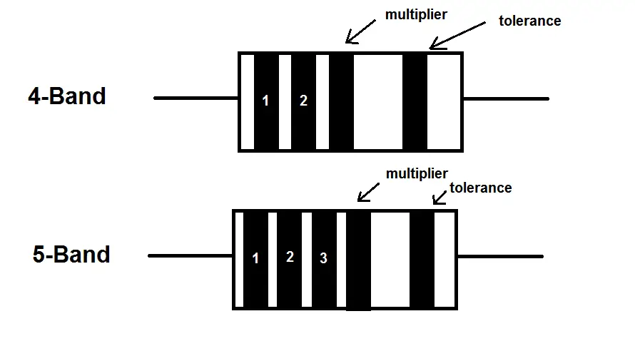
Note, the last color band (tolerance value) is usually spaced apart further from the other colours so that there is no confusion when looking at the resistor from different points of view.
Below is a table of the colors associated with resistor color codes and their values.
| Color | Digit | Multiplier | Tolerance (%) |
| Black | 0 | 1 | |
| Brown | 1 | 101 | 1 |
| Red | 2 | 102 | 2 |
| Orange | 3 | 103 | |
| Yellow | 4 | 104 | |
| Green | 5 | 105 | 0.5 |
| Blue | 6 | 106 | 0.25 |
| Violet | 7 | 107 | 0.1 |
| Grey | 8 | 108 | |
| White | 9 | 109 | |
| Gold | 10-1 | 5 | |
| Silver | 10-2 | 10 | |
| (none) | 20 |
The multiplier is the value you multiply the other numbers by to get the total resistance.
For example, let’s say we had a 4-band resistor with the colours, red, orange, yellow, and green.
- 1st digit = Red = 2
- 2nd digit = Orange = 3
- Multiplier = Yellow = 104 (10000)
- Tolerance = Green = 0.5%
Therefore, the total resistance would be 23 x 10000 = 230000 ohms (or 230kohms), with a tolerance of 0.5%.
Another way of figuring out a resistor is to use a Multimeter, which has the ability to measure the resistance of materials (mainly conductors).
Sometimes reading colour codes can be quite cumbersome, so using a multimeter might be the easier option.
Are resistors the only components that have resistance?
No, every component has some sort of resistance. As we saw earlier, all materials have resistance depending on the type of material as well as their length and area.
However, they are not specifically designed to have a certain amount of resistance like resistors are. The resistance values are random.
When designing circuits, the total resistance needs to be taken into consideration. Most of the time, the total resistance of components (other than resistors), can be small enough that they won’t affect the overall resistance of the circuit.
Does a resistor have constant resistance?
No, the resistance of a resistor is affected by Temperature.
The resistance increases as the temperature increases regardless of the material as well as the fixed length and area of the resistor (however, as we saw earlier, some fixed value resistors are more resistant to changes in temperature than others).
This happens because the atoms within a material get excited as the temperature increases. This causes the atoms to move about more hastily, making it harder for electrons to get through.
Superconductivity is a phenomenon whereby you subject conductors to extremely low temperatures, and almost eliminate all resistance of the conductor.
The relationship between temperature and resistance can be summarized by the parameter known as Temperature Coefficient of Resistance (TCR).
TCR shows the change in resistance as a function of the ambient temperature (this relationship is linear).


