
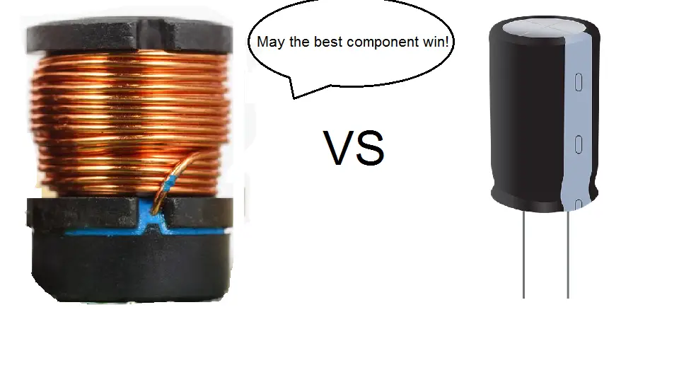
Capacitors and Inductors are passive electronic components that can be found in many circuits. Each has their own unique abilities and characteristics that are beneficial in many applications.
These two components share a similar ability, which is to store energy. This is why sometimes they can be confused for being the same.
However, each of them goes about doing so in different ways.
The major differences between a capacitor and inductor include:
- Energy storage
- Opposing current vs Opposing voltage
- AC vs DC
- Voltage and current lag
- Charging and Discharging rates
- Applications
- Units
This article shall take a closer look at all these differences between the capacitor and inductor.
Deeper look at a capacitor and inductor
To better understand the differences between the two components, it will benefit you to first learn a bit more about each component individually.
Things like their purpose, working principle, construction, etc.
However, if you already have a knowledge of both components, you can skip straight to the capacitor vs inductor section.
Let’s start with the capacitor.
What is a capacitor
Capacitors are one of the three fundamental passive components used in electrical and electronic circuits (the other two being resistors and inductors).
A capacitor is a two terminal passive component which has the ability to store electrostatic energy within an electric field when current flows through it.
The main purpose of a capacitor is to oppose changes in voltage.
They have many applications in a circuit with the most common being energy storage, voltage spike suppression and signal filtering.
There are two types of capacitors; Polarised and Non-Polarised.
A non-polarised capacitor is like a resistor and the orientation of its terminals does not matter when placing it in a circuit.
Polarized capacitors however, have a positive and negative terminal, which means that they must be placed the right way round in a circuit.
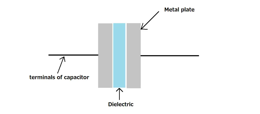
Construction of capacitor
A capacitor is constructed using two metal plates which are separated by an insulating material known as the dielectric as seen in the diagram below.
The dielectric can be a range of insulating materials (inhibits the flow of current) which can include;
- Air
- Paper
- Glass
- Rubber
- Plastic
- Ceramic
While the two metal plates are made from conductive materials (allows the flow of current) and can include metals such as;
- Aluminium
- Tantalum
- Silver
- Copper
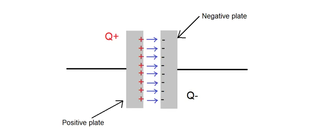
Working principle of a capacitor
The simplest form of a capacitor is two metal plates separated by a dielectric as we saw earlier.
When a voltage is applied to a capacitor, an electron is added to one plate making it negatively charged.
This electron has an electric field which repels other electrons. It travels through the space between the plates and bumps the electrons off the other plate making it positively charged.
As the process increases, the amount of electrons added to the first plate increases thus increasing its negative charge, which in turn increases the induced positive charge on the second plate.
Eventually, the amount of negative charge on the first plate is going to reach a maximum value which will prevent the battery from adding more electrons.
The capacitor is said to be fully charged at this point, and its electric field will be at its strongest.
Since electric fields radiate away from positive charges and towards negative ones, an electric field will point across the gap between the two metal plates in straight lines.
How much energy is stored within a capacitor’s electric field
When a capacitor is connected to a power source (like a battery), it stores the received energy in the form of the electric field which we have just discussed.
The amount of energy stored in a capacitor’s electric field comes down to a singular formula and a couple of variables.
Without going into too much detail of its derivation, below is the formula used to calculate the amount of energy stored within a capacitor’s electric field.

W represents energy, C is capacitance and V is voltage.
Let’s take a look at how capacitance affects the magnitude of a capacitor’s electric field.
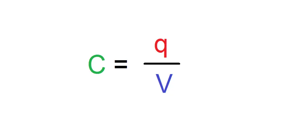
Capacitance is a crucial part of a capacitor which determines its ability to store electrical energy in an electric field.
As you just saw before, when a voltage is applied to a capacitor, a fixed amount of positive (q+) and negative (q-) charges build up on either plate of the capacitor.
Using the value of voltage (V) and total amount of charge (q), we can calculate the total capacitance (C).
What is an inductor
Now let’s learn about the Inductor.
While not as common as the resistor or capacitor, inductors are still widely used in many electrical and electronic circuits for their unique abilities.
An inductor is a two terminal passive component which has the ability to store energy in the form of a magnetic field when current flows through it.
The main purpose of an Inductor is to oppose any sudden changes in current.
They slow down current spikes and surges by storing this extra energy in their magnetic field and then slowly releasing it back into the circuit.
Its ability to resist this change can be shown by its Inductance which is the ratio of voltage and current change within the inductor.
Inductance is given in the unit of Henry (H).
Construction of inductor
If you were to look at a circuit schematic which had an inductor, you would see a symbol as seen below.
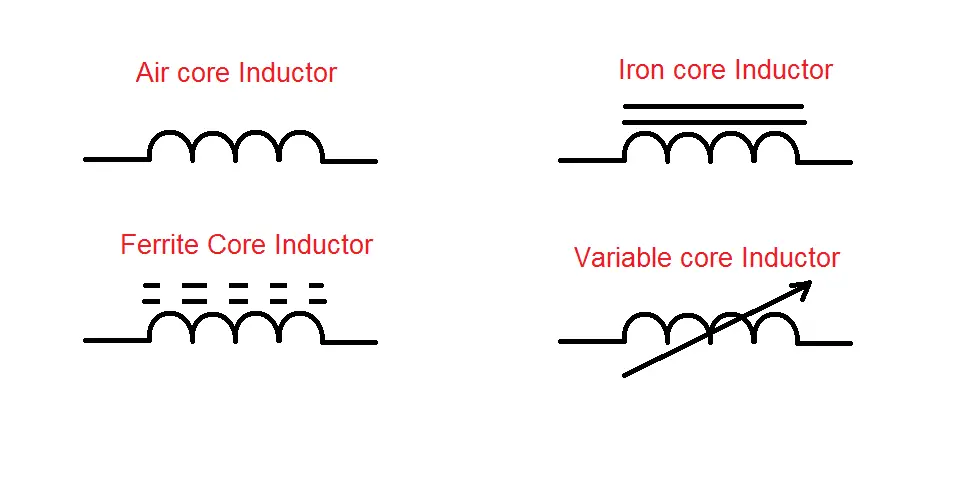
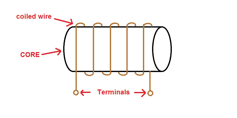
The construction of a basic Inductor involves a wire that is coiled around a core material.
This core material can vary depending on the needs of the application and can include either magnetic iron or ferrite core (amongst the most common).
An insulated copper wire is the choice of material for the wire wrapped around the core.
There are many variables that can alter the inductance of an inductor which include; number of turns (of the wire), spacing between turns, number of layers of turns, material of core, magnetic permeability of core material, size, and shape.
Working principle of a inductor
So how does an inductor work?
As we just saw, an inductor is composed of a wire coiled around a core. The working principle of an inductor can be better understood if we uncoil this wire into a straight wire.
When current flows through a straight wire, a magnetic field is generated around that wire as can be seen in the image below.
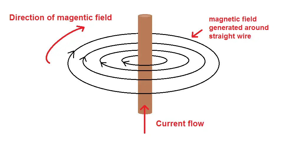
The strength of the magnetic field is directly proportional to the current. So, increasing the current will increase the magnitude of the magnetic field.
Also, the strength of the magnetic field is strongest closest to the wire. An inductor utilises this concept. It consists of wire wrapped in a coil formation around a central core.
This means that when current flows through the inductor, a magnetic field is generated within the inductor.
Since the wire is coiled, the magnetic field is multiplied.
The relationship between current and the strength of the magnetic field are directly proportional. So, an increase in current will see an increase in the strength of the magnetic field.
How much energy is the inductor capable of storing?
As you can imagine, the amount of energy stored in the magnetic field of a straight wire is going to be far less compared to that of a wire that has been coiled.
This is due to the fact that the magnetic field (and therefore magnetic energy) is increased as a straight wire is coiled.
The strength of a magnetic field around a straight and coiled wire is known as magnetic field strength or H.
Below are the two formulas for the H in a straight and coiled wire.
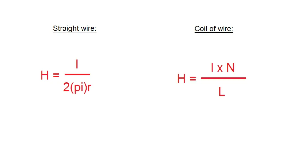
H – strength of magnetic field ampere/turn
N – number of turns of coil
I – current flowing through in Ampere (A)
L – length of coil (in metres)
By looking at the equation for a straight wire you can see that the only way to increase the magnetic strength is to increase the amount of current, or material of wire.
However, when it comes to a coil, you have many more options to increase magnetic strength which include;
- Number of turns contained within the coil
- How much current is flowing
- Type of core material used for the inductor
- Cross sectional area of wire
Capacitor vs Inductor -7 key differences
Now that we know a bit more about both the capacitor and inductor, we can have a discussion about the key differences between the components.
Capacitor vs Inductor key difference #1: Energy Storage
The first key difference between a capacitor and inductor is energy storage.
Both devices have the capability to store energy, however, the way they go about doing so is different.
A capacitor stores electrostatic energy within an electric field, whereas an inductor stores magnetic energy within a magnetic field.
Capacitor vs Inductor difference #2: Opposing current or voltage
As we just saw, both devices have the ability to store energy either in an electric field (capacitor) or magnetic field (inductor).
This energy storage has a purpose which is to either oppose current or oppose voltage.
A capacitor opposes changes in voltage, while an inductor opposes changes in current.
Capacitor vs Inductor difference #3: AC or DC
Electrical and electronic applications can be divided into two major categories; Alternating Current (AC) or Direct Current (DC).
Alternating Current deals with current whose direction and magnitude varies periodically (just like a sinusoidal wave).
Direct Current on the other hand has only one direction and magnitude. It does not change periodically.
When it comes to capacitors and inductors, each deals with these currents differently.
Capacitors allow AC currents to pass, but prevents DC currents from flowing.
Inductors on the other hand allow DC currents to pass, but block AC.
Capacitor vs Inductor difference #4: Voltage and Current Lag
When current flows through a circuit it is going to encounter three types of impedances (opposition), which are caused by Resistance (R), Inductance (L), and Capacitance (C).
Resistance does not pose much opposition so voltage and current are in phase.However inductors and capacitors do provide impedances which offset voltage and current.
When voltage rises in a circuit that has an inductor, a rise in voltage sees a rise in current. This rise is slightly delayed due to Back EMF caused by the inductor.
This means as voltage rises and falls, current rises and falls a fraction of a second later.
So current lags voltage in an Inductor.
The story is much different for circuits that contain capacitors. When current rises, voltage rises, but when it falls, the fall of voltage is slightly delayed.
So voltage lags current in a capacitor.
Capacitor vs Inductor difference #5: Charging and discharging rate
So, capacitors store electrical energy, and inductors store magnetic energy. However, this energy build up does not happen instantaneously.
Also, the release of energy takes time.
The build up, and release of energy for a capacitor and inductor are known as their charging and discharging rates respectively.
A capacitor’s charge and discharge rate is governed by the RC Time Constant, whereas an inductor’s charge and discharge rate is given the RL Time Constant.
Where R is the value of the resistor in series with the components, C is the capacitance and L is the inductance.
Capacitor vs Inductor difference #6: Applications
Both the capacitor and inductor have unique abilities.
This means that each component will have its own unique purpose for certain applications. Below shows the different applications for a capacitor and inductor.
Capacitor applications:
- Power conditioning
- Signal coupling/decoupling
- Noise filtering
- Remote sensing
- Power factor correction
Inductor applications:
- Choking
- Blocking
- Attenuation
- High frequency noise filtering/Smoothing
- Energy transfer (DC-DC or AC-DC)
Capacitor vs Inductor difference #7: Units
The last major difference between a capacitor and inductor is their Units.
Units are found in every aspect of science and engineering. It defines the magnitude of quantity which is brought about by convention or law.
This unit will be universally recognised.
For example, the unit for current is Amperes (Amps), represented by the letter I.
The amount of energy a capacitor is capable of storing is dependent on its Capacitance (C), which has the units of Farads further represented by the letter F.
While the amount of energy an inductor is able to store is dependent on its Inductance (L), which has the units of Henry with the symbol H.
Do a capacitor and inductor share any similarities?
We have just seen the major differences between a capacitor and inductor. But, these two components do share some similarities in their overall purpose.
The first thing in common is that both components have the ability of storing energy even if the type of energy stored is different.
Next, both components use this stored energy to oppose the rise of a force, voltage for a capacitor, and current for an inductor.
Finally, both components have charging and discharging rates. This means that voltage and current does not change instantaneously for either.
Which is better; a capacitor or inductor?
A capacitor is not better than an inductor, and an inductor is not better than a capacitor.
As you have just seen, while both components share a similar purpose (energy storage), they differ in many other characteristics.
Their differences are what gives each of them unique abilities for different applications.
So, it really depends on the needs of the application. You cannot say one is better than the other.
Can you use a capacitor and inductor together?
Yes, a capacitor and inductor are commonly used in the same circuit.
An LC circuit is a circuit that contains an inductor and capacitor which is also commonly known as a tuned, tank, or resonant circuit.
This type of circuit has the specific purpose of generating signals at a particular frequency, or to receive a complex signal at a particular frequency.
Common applications for LC circuits include radios, radio equipment, tuners, filters, frequency mixers and oscillators.


